2024年8月17日 星期六

C語言存取二維字元陣列的方法

 #include <stdio.h>

#include <stdlib.h>


#define ROW 4

#define LEN 5

char array[ROW][LEN] = {

    {'P', 'I', 'C', '1', '6'},

    {'P', 'I', 'C', '1', '8'},

    {'P', 'I', 'C', '2', '4'},

    {'D', 'S', 'P', 'I', 'C'}

};

char *ptr = &array;

unsigned char row, column;

int main(void)

{

    printf("access using array method\n");

    for(row = 0; row < 4; row++)

    {

        for(column = 0; column < 5; column++)

        {

            printf("%c", array[row][column]);

        }

        printf("\n");

    }

    printf("----------------------------------\n");

    printf("access using array method\n");

    for(row = 0; row < ROW; row++)

    {

        for(column = 0; column < LEN; column++)

        {

            printf("%c", *ptr++);

        }

        printf("\n");

    }

    printf("access using array + pointer method\n");

    for(row = 0; row < 4; row++)

    {

        for(column = 0; column < 5; column++)

        {

            printf("%c", *(array[row] + column));

        }

        printf("\n");

    }

    printf("----------------------------------\n");

    printf("access using pointer method\n");

    for(row = 0; row < 4; row++)

    {

        for(column = 0; column < 5; column++)

        {

            printf("%c", *(*(array+row)+column));

        }

        printf("\n");

    }

    printf("----------------------------------\n");

    printf("access using ptr point to array method\n");

    for(row = 0; row < 4; row++)

    {

        for(column = 0; column < 5; column++)

        {

            printf("%c", *(ptr + (row * 5) + column));

        }

        printf("\n");

    }


    while(1)

    {


    }

    system("pause");

    return 0;

}


C語言存取二維字串陣列(使用陣列或指標)

 #include <stdio.h>

#include <stdlib.h>


char str[4][6] = {

    {"PIC16"},

    {"PIC18"},

    {"PIC24"},

    {"DSPIC"}

};


unsigned char row, column;


int main(void)

{

    printf("access string using array method\n");

    for(row = 0; row < 4; row++)

    {

        column = 0;

        while(str[row][column] != 0x00)

        {

            printf("%c",str[row][column]);

            column++;

        }

        printf("\n");

    }

    printf("----------------------------------\n");

    printf("access string using array + pointer method\n");

    for(row = 0; row < 4; row++)

    {

        column = 0;

        while((*(str[row]+column)) != 0x00)

        {

            printf("%c", *(str[row]+column));

            column++;

        }

        printf("\n");

    }


    while(1)

    {


    }

    system("pause");

    return 0;

}


C語言存取字串指標陣列

 #include <stdio.h>

#include <stdlib.h>


char *str[4] = {"PIC16", "PIC18", "PIC24", "DSPIC"};


unsigned char row = 0, column = 0;


#define NULL 0x00


int main(void)

{

    printf("access string using pointer method\n");

    for(row = 0; row < 4; row++)

    {

        column = 0;

        while(*(*(str+row) + column) != NULL)

        {

            printf("%c", *(*(str+row) + column));

            column++;

        }

        printf("\n");

    }

    printf("----------------------------------------\n");


    printf("access string using array+pointer method\n");

    for(row = 0; row < 4; row++)

    {

        column = 0;

        while(*(str[row]+column) != NULL)

        {

            printf("%c",*(str[row]+column));

            column++;

        }

        printf("\n");

    }


    while(1)

    {


    }

    system("pause");

    return 0;

}


2023年11月30日 星期四

STM32於IAR 9.3以後的版本將uart導向至printf

首先,請先參考如以下IAR提供的"在IAR Embedded Workbench中实现打印输出技術資料"

https://www.iar.com/cn/knowledge/support/technical-notes/general/implementing-printf-output/

本文要說明的是重新定向到MCU的周邊(UART)


STM32在IAR9.2以前的版本printf時,在main.c的主程式之前通常會加入如以下的程式

#ifdef __GNUC__

/* With GCC, small printf (option LD Linker->Libraries->Small printf

   set to 'Yes') calls __io_putchar() */

#define PUTCHAR_PROTOTYPE int __io_putchar(int ch)

#else

#define PUTCHAR_PROTOTYPE int fputc(int ch, FILE *f)

#endif /* __GNUC__ */


並執行以下宣告如於主程式之後

/**

  * @brief  Retargets the C library printf function to the USART.

  * @param  None

  * @retval None

  */

PUTCHAR_PROTOTYPE

{

  /* Place your implementation of fputc here */

  /* e.g. write a character to the USART2 and Loop until the end of transmission */

  HAL_UART_Transmit(&UartHandle, (uint8_t *)&ch, 1, 0xFFFF);

  return ch;

}

但是在IAR9.32以後,已經不支援此方式了,因此在這邊大致上來記錄一下我查到的資訊與方法跟同樣遇到問題的人分享,

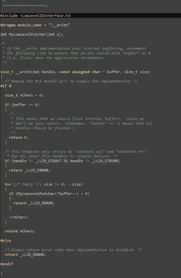
1.先到IAR安裝後的資料夾找出write.c,下圖是write.c原始的內容


2.COPY write.c到自行設定的專案資料夾內

3.在您的IAR專案內加入write.c

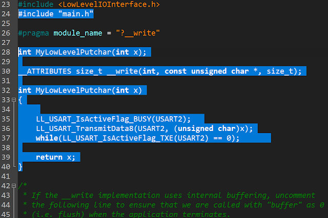
4.修改write.c以下內容,把main.h這個head file include進來,然後把您的UART底層驅動的函式放在MyLowLevelPutChar內,大致上就可以了,記住您的main.h裡面必須include stdio.h進來,才會有printf相關的函式,由於我用的底層選擇為STM32K的LL,您也可以換成STM32 HAL或是Standard Peripheral Libraries的底層函式


2023年11月20日 星期一

如何透過示波器存下來的波形檔案進行類比電路模擬

在設計電路的時候,常常會遇到雜訊問題,於是我們就會在電路板上進行跳線修改,增加元件增加電容之類的工作,但如果是要增加一個n階的濾波器,有可能因為手工難以修改或增加,而且也無法確定增加的電路是否能正常工作,因此我會藉由電路模擬軟體來協助分析,但是特定的雜訊可能無法在模擬軟體中生成,怎麼辦??

我們可以透過在示波器錄下來波形的圖檔,轉存成.csv/.xls/.txt/.dat或是ASCII files, 然後存在電腦另存.txt file, 其實裡面的內容不外乎是time(second)與amplitude(volt),也就是時域裡的時間跟振福!

有了這個波形檔案我們就可以透過模擬軟體來實現雜訊濾波器電路的模擬了,首先將示波器存好的檔案轉到電腦中存成.txt,去除檔案中的文字,例如time(second)與amplitude(volt)之類的相關文字,只留示波器X/Y兩軸所錄下來的數字,該數字可能有科學符號,例如E-02,代表是10^-2次方,這必須保留以免,數值不正確!

我所使用的模擬軟體是Microchip授權給使用者免費使用的MINDI, 屬於Simetrix/Simplis這類的模擬軟體,首先需要設計濾波器,這部分有兩種方法,一是照濾波器公式計算,二是用類比濾波器軟體幫你設計,建議可以使用Analog Filter Wizard網頁版,假設預計設計的是High Pass Filter,就選擇如下圖對應的Filter type


然後進入Specification之後選擇填入Passband與Stopband,並選擇Filter Response, Filter Response與電路複雜度跟濾波器效果有很大的關係,當然成本也會有所增加


接下來進入Components選擇電壓,就會跳出濾波器電路+參考電壓的電路,然後把電路記下來繪製到慣用的模擬軟體,可以是CADENCE ORCAD PSPICE / SIMETRIX / ADI LTSPICE / MICROCHIP MINDI / TI TINA等等之類的軟體,我用的是MICROCHIP MINDI, 因為免費且容易使用,但有元件數量的限制,使用者自行斟酌!


以下是我的波形.txt檔, 用來放進去MINDI模擬軟體的PWLFILE


設定好模擬的選項(暫態Transient),我的雜訊加訊號是100ms這麼長,因此時間設100ms,就可以開始模擬了!
如下圖可以看到紅色波形是示波器從實際的電路板電路中錄下來的波形加雜訊,經過濾波之後是綠色的波形,雖然訊號變小了,但很明顯的SNR變得好很多,若再經過下一級放大就可以得到足夠大的訊號了!
整個電路方塊大約是這樣:
Input --> HPF --> Amplifier output


2020年9月4日 星期五

ADC two point calibration

使用MCU時常會有不準確的問題,造成量測不精準的狀況,可以透過兩點式校正ADC的方法,將ADC的Gain error及Offset error校正回來,取得需要的精確度。

要進行ADC兩點校正方法不難,首先在MCU的部分需要有VREF輸入可以使用,在不透過人工使用Calibration Source的情況下,利用ATL431B Grade(0.5%)輸出2.5V(VREF)做ADC參考電壓,然後再利用ATL431輸出的2.5V電壓做90%*VREF及10%*VREF兩個電壓點分別進入AN0與AN1,利用AN0、AN1兩點電壓做校正,假設ADC的解析度為12 bit,2點校正實際方式如下:

/*

VREF = 2.5V

The two calibration points are chosen at V1 = 2.5*10k/(10k+100k); V2 = 2.5*100k/(10k+100k)

The ideal ADC output values at V1 and V2 are represented as Ci1 and Ci2.

Ci1 = V1 * 4096 / 2.5 = 372; Ci2 = V2 * 4096 / 2.5 = 3724

Assume Ca1 = 404, Ca2 = 3847

The actual ADC output values at V1 and V2 are represented as Ca1 and Ca2.

The gain and offset error will be calculated using the equation of a straight line     y = mx + b, Where m is the slope of the line and b is the offset.

The gain error can be calculated as the slope of the actual ADC output divided by the slope of the ideal ADC output.

Gain Error = (Ca2 – Ca1) / (Ci2 – Ci1) = (3847 – 404) / (3724 – 372) = 1.027(positive gain error)

b = y – mx

Offset error = Cal – (Gain error * Ci1) = 404 – (1.027 * 372) = 22(positive offset error)

GAINCORR(Gain correction) = 4096 / Gain error = 4096 / 1.027 = 3988

OFFSETCORR = offset error = 22

Adc result = (Conversion value – OFFSETCORR) * (GAINCORR/4096)

Ca1 = (404 – 22) * (3988 / 4096) = 372

Ca2 = (3847 – 22) * (3988 / 4096) = 3724

*/    

#define CI1 372

#define CI2 3724

 unsigned long int Ca1, Ca2;

long int Ci1 = CI1, Ci2 = CI2;

unsigned int GainError;

int OffsetError;


Ca1 = Adc_Read(ACS_AN1, VBG_DIS);

Ca2 = Adc_Read(ACS_AN2, VBG_DIS); 


/* y = mx + b, m = slope = (y2-y1) / (x2-x1), y2 = Ca2, y1 = Ca1, x2 = Ci2, x1 =  Ci1*/

GainError = (unsigned int)(((Ca2-Ca1) << 12) / (Ci2 - Ci1)); // scale to 4096

/* b = y - mx */

OffsetError = (int)(Ca1 - (Ci1 * GainError >> 12));

OffsetCorr = OffsetError;


/* GainCorr = 4096 * (1/GainError) = 4096 * 4096 / GainError */

GainCorr = (unsigned int)(4096ul * 4096 / GainError);


void MeasureVoltage(void)

{

        static unsigned int SumOfMovAvg = 0;

        static unsigned int MovAvg_Buffer[8] = {0};  // Moving average buffer

        static unsigned char Index = 0;                       // Moving average index

        unsigned char cnt = 0;

        unsigned long int Temp;

    unsigned int result;


    MovAvg_Buffer[Index++] = Adc_Read(ACS_AN0, VBG_DIS);

        if(Index == 8)

        {

                Index = 0;

                FLAGbits.MovingAvgOutput = 1;

        }


        SumOfMovAvg = 0;

        if(FLAGbits.MovingAvgOutput)

        {

                for(cnt = 0; cnt < 8; cnt++)

                        SumOfMovAvg += MovAvg_Buffer[cnt];                                       

                Temp = (SumOfMovAvg >> 3);

        }

        else

        {

                for(cnt = 0; cnt < Index; cnt++)

                        SumOfMovAvg += MovAvg_Buffer[cnt];                                       

                Temp =  MovAvg_Buffer[Index-1]; //Temp = (SumOfMovAvg / Index);     

        }      

        result = (unsigned int)((unsigned long int)(Temp - OffsetCorr) * GainCorr >> 12);

        // result is the ADC output after two point calibration

}

2019年7月5日 星期五

如何透過校正提升SAR ADC量測電壓的精確度

通常做量測產品的開發時,很多人沒有校正的習慣,這種問題對於做電壓的量測工具來說尤其重要,以開發電瓶量測工具來說,電壓精準度很重要,誤差0.1V對量測電池內阻來說差異就很大了,所以我來提供幾個需要注意的地方,讓你可以使用SAR ADC也可以精準!

撇開硬體的濾波電容等設計不說,要準確的使用ADC,有幾件事要注意:
1.精準的參考電壓源:
假設使用12-bit ADC,可以使用5V、4.096V、2.5V、2.048V的參考電壓,參考電壓越小時ADC的輸入就可能需要有分壓電阻,建議盡量使用跟ADC解析度可以整除的參考電壓,例如12-bit = 2^12 = 4096, 4.096 / 4096 = 1mV = 1LSB,這樣在計算電壓上可以整除,所以誤差較小,選擇參考電壓時要注意精度,盡量選擇0.5%的參考電壓源,例如
2.控制分壓電阻的精度:
     ✮假設電壓輸入12V,分壓電阻使用91k(+-1%)及13k(+-1%),最大的誤差量會發生在91k(+1%)搭配13k(-1%)及91k(-1%)搭配13k(+1%)這兩個組合,12*(12870/(91910+12870))=1.4739及12*(13130/(90090+13130)) = 1.5264,乘上分壓比例8則分別為11.79及12.21,假設在板子上發生這電壓不準確的時候,我們可以透過電壓校正將電壓補償回來,例如12.00/11.79 = 1.0178(GAIN,分壓增益),假電壓為14V,則14*(12870/91910+12870))= 1.7196,反推分壓後為13.75V,且13.75*1.0178 = 14.00V
      ✭但是,非理想的ADC具有INL及DNL誤差,因此分壓增益越大,帶有INL及DNL誤差的ADC Code計算成實際電壓之後再乘上增益會使誤差加大,也就是說(IDEAL ADC+ERR)*GAIN=(IDEAL ADC*GAIN) +(ERR*GAIN), ERR*GAIN會把誤差放大,且通常發生在電壓不是在校正點的地方,解決方法就是將分壓增益縮小,實際的方法就是控制分壓電阻的精度,如91k(+-0.1%)與13k(+-0.1%), 12*(12987/(91091+12987))=1.4972, 1.4972*8 = 11,977, 12/11.977=1.0019,也就是ADC本身誤差*GAIN最多會與理想誤差值相差0.0019倍


     DNL = |[(VD+1- VD)/VLSB-IDEAL - 1] | , where 0 < D < 2N - 2.
      INL = | [(VD - VZERO)/VLSB-IDEAL] - D | , where 0 < D < 2N-1.


      3.選擇適合的校正電壓點:
      將校正電壓點移到最常量測的電壓點,以一般12V電瓶來說是13~12V之間,因此將校正點由12V移到12.5V

PADS CAM Directory過多路徑刪除方法

 可以在C:\MentorGraphics\9.5PADS\SDD_HOME\Programs底下的powerpcb.ini以文字編輯器開啟,搜尋[CAMDirExt],將底下的路徑刪除即可